Email :sales@beondt.com
What Is A Transformer?
Power supply design is an unavoidable issue in current hardware product design. In the previous article, we have discussed several types of DCDC converters. Today, we will explore another low loss buck boost scheme: transformers.
A transformer is an electromagnetic component of a circuit used to change the alternating voltage. It can convert one AC voltage into another through electromagnetic conversion while keeping the power basically unchanged.
Application of Transformers
In the power system, transformers are widely used for increasing or decreasing voltage. It can be used for electrical isolation, significantly improving system safety and reducing the risk of electric shock; The use of transformers also achieves grounding system separation, which can effectively suppress common mode noise; Provided DC isolation to protect sensitive circuits; Simultaneously achieving voltage conversion and impedance matching while isolating; Restricting the scope of fault propagation and improving system reliability; Improved electromagnetic compatibility, helping to meet EMC requirements; Support multiple winding applications and adapt to complex system requirements; It can also be used for special applications such as signal coupling, phase adjustment, and harmonic suppression. These advantages make transformers an indispensable key component in fields such as power, industry, healthcare, and communication, providing solid guarantees for the safety, efficiency, and reliability of modern electrical systems and greatly promoting the development of modern power systems.
Working Principle of Transformer
The working principle of transformers is based on the law of electromagnetic induction. Its electromagnetic structure consists of two or more coils wound around the same iron core. In practical structures, there will be insulation materials used between windings and between windings and iron cores, as well as between the casing and cooling system.
When AC current passes through the primary coil, an alternating magnetic field is generated in the iron core. This alternating magnetic field will induce voltage in the secondary coil. By adjusting the turns ratio of the primary and secondary coils, different output voltages can be obtained. Usually, transformers have more than one circuit, for example, single-phase transformers have two circuits, while three-phase transformers have six circuits.
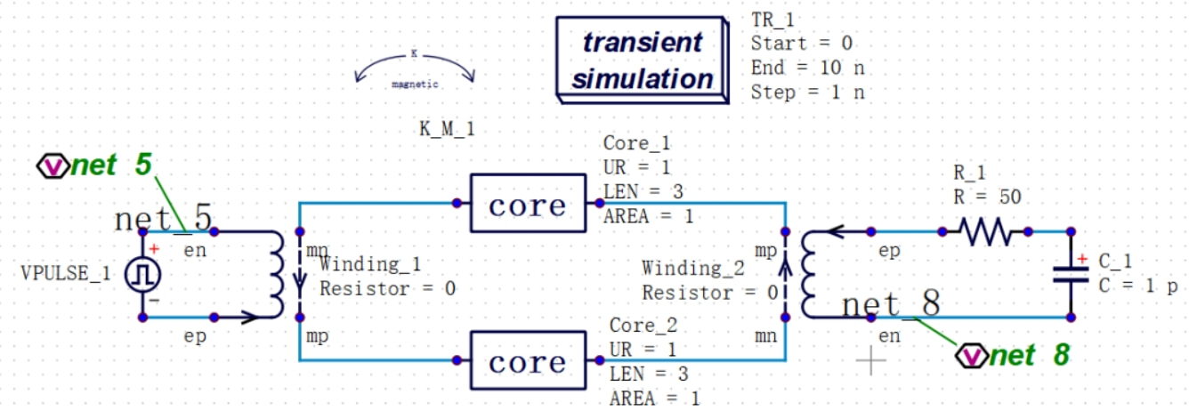
The iron cores and winding materials of different transformers vary greatly. Julin Technology's PowerExpert supports simple and flexible custom transformer construction. Custom transformers can be built using winding, core or non-linear core, and winding binding (K_Magnatic) devices. The ideal magnetic core supports setting magnetic permeability, cross-sectional area and length, while the nonlinear magnetic core supports setting shape parameters, magnetic domain wall bending constant, hysteresis loss coefficient, saturation magnetization intensity and other coefficients. The magnetic core and winding are set to belong to the same transformer through winding binding devices.
Build a simple custom transformer using PowerExpert software, where the winding has 5 turns and 10 turns, as shown in the following figure:

Perform transient simulation, and the simulation results obtained are shown in the following figure:

Our hours
Mon to Fri: 9 AM - 7 PM (GMT+8)